-
Mail us
contact@tiger-transformer.com -
Phone us
(+86)15655168738 -

Mail us
contact@tiger-transformer.comPhone us
(+86)15655168738
1. Definition of switching power supply
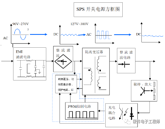
After the input AC voltage (AC) is rectified and filtered, a high-voltage DC voltage (DC=1.4AC) can be obtained. This voltage is connected to the switching element and used as a switch in 20KHZ~100KHZ high frequency state. At this time, the DC high voltage will be cut into a high-frequency square wave signal. This square wave signal can obtain the pre-set voltage value on the secondary side through the power isolation transformer, and then the required voltage can be obtained through rectification and filtering. DC output voltage. The block diagram of the switching power supply is as follows:
2. Switching power supply Classification
Switching power supply can be divided into four categories according to the type of input voltage and output voltage, namely DC-DC, AC-DC, DC-AC, AC-AC. Among them, DC-AC and AC-AC are seldom seen in practical applications, so the description in this article is omitted.
2.1 DC/DC conversion
Converting a fixed DC voltage into a variable DC voltage is also called DC chopping. There are two working modes of the chopper, one is the pulse width modulation mode, Ts is unchanged, and the ton is changed (common), and the other is the frequency modulation mode, the ton is unchanged, and Ts is changed (easy to generate interference). Its specific circuit consists of the following categories:
(1) Buck circuit——a step-down chopper, whose output average voltage Uo is smaller than the input voltage Ui, and has the same polarity.
(2) Boost circuit - boost chopper, its output average voltage Uo is greater than the input voltage Ui, and the polarity is the same.
(3) Buck-Boost circuit - buck or boost chopper, its output average voltage Uo is greater than or less than the input voltage Ui, the polarity is opposite, and the inductance is transmitted.
(4) Cuk circuit - a step-down or step-up chopper, whose output average voltage Uo is greater than or less than the input voltage UI, with opposite polarity and capacitive transmission.
2.2 AC/DC conversion
AC/DC conversion is to convert AC to DC, and its power flow can be bidirectional, and the power flow from the power source to the load is called "rectification" , the power flow from the load back to the power supply is called "active inverter". The input of the AC/DC converter is 50/60Hz alternating current. Because it must be rectified and filtered, a relatively large filter capacitor is essential. At the same time, due to safety standards (such as UL, CCEE, etc.) and EMC directives Restrictions (such as IEC, FCC, CSA), the AC input side must add EMC filtering and use components that meet safety standards, which limits the miniaturization of the AC/DC power supply. In addition, due to the internal high frequency, high voltage, and large current The switching action makes it more difficult to solve the problem of EMC electromagnetic compatibility, which also puts forward high requirements for the design of internal high-density installation circuits. For the same reason, high voltage and high current switches increase the power consumption and limit AC /DC converter modularization process, so it is necessary to adopt the power system optimization design method to make its work efficiency reach a certain degree of satisfaction.
3. Common topologies
3.1 Single-ended flyback converter
3.1.1 Circuit topology

3.1.2 Circuit principle
The transformer T1 is used to isolate and transfer stored energy The role of Np is to store energy when the switch tube Q is turned on, and Np releases energy to Ns when the switch tube Q is turned off. A low-pass filter composed of an inductor Lo and two Co capacitors should be added at the output end, and an RCD leakage inductance peak absorption circuit composed of Cr, Rr and Dr should be provided at the primary stage of the transformer. The output loop needs a rectifier diode D1. Since the transformer uses a magnetic core with an air gap, its copper loss is relatively large, and the temperature of the transformer is relatively high. And its output ripple voltage is relatively large. But its advantage is that the circuit structure is simple, it is suitable for the power supply below 200W and the multi-channel output intermodulation characteristics are relatively good.
3.2 Dual-tube flyback converter
3.2.1 Circuit topology

3.2.2 Circuit principle
The transformer T1 plays the role of isolating and transferring stored energy, that is, when the switch tubes Q1 and Q2 are turned on, Np Energy is stored, Np releases energy to Ns when the switching tubes Q1 and Q2 are turned off, and the leakage inductance of Np will return to the input through D2 and D3, which can save the RCD leakage inductance peak absorption circuit. A low-pass filter consisting of an inductor Lo and two Co capacitors should be added at the output end. The output circuit needs to have a rectifier diode D1 (it is better to use a rectifier with a fast recovery time).
3.2.3 Working characteristics
a. Under any working conditions, in order to make the voltage of the two adjustment tubes not exceed Vs+Vd (Vs: input voltage; Vd : The forward pressure drop of D2 and D3,), D2 and D3 must be fast recovery tubes (of course it is better to use ultra-fast recovery tubes).
b. At the beginning of the flyback, the energy stored in the leakage inductance of the primary side Np will be fed back to the input through D2 and D3, and the system energy loss will be small and the efficiency will be high.
c. Compared with the single-ended flyback converter, there is no need for an RCD snubber circuit; the power device can choose a lower withstand voltage value; the power level will also be large.
d. At light load, if there is too much energy stored in the primary winding of the transformer during the "on" period, the excessive energy energy will be fed back to the input during the "off" period .
3.3 Single-ended forward converter
3.3.1 Circuit topology

3.3.2 Circuit principle
The transformer T1 plays the role of isolation and voltage transformation, and an inductor Lo (freewheeling current) should be added at the output end Inductance) plays the role of energy storage and transmission, and the transformer primary needs to have a reset winding Nr (I have doubts about some reference books on this point, of course it is the best, and the transformer pin position is considered in practical applications). In actual use, I also found that this winding can also be replaced by an RCD absorption circuit. If the auxiliary power supply of the chip is supplied by a flyback, part of the peak voltage of the regulator tube (a considerable part of the reset winding) can also be cut off. The output loop needs a rectifier diode D1 and a freewheeling diode D2. Since the transformer uses a magnetic core without air gap, its copper loss is small and the temperature rise of the transformer is low. And its output ripple voltage is small.
3.4 Dual-tube forward converter
3.4.1 Circuit topology

3.4.2 Circuit principle
The transformer T1 plays the role of isolation and voltage transformation, and an inductor Lo is added at the output end (continued Current inductance) plays the role of energy storage and transmission, and the transformer primary does not need a reset winding, because the conduction of D1 and D2 limits the voltage that the two regulators can withstand when they are turned off. The output circuit needs to have a rectifier diode D3 and a freewheeling diode D4 (D3 and D4 are preferably rectifiers with fast recovery time). The output filter capacitor Co should be selected with low ESR (equivalent resistance) and large capacity, which is conducive to reducing the ripple voltage (of course, this is also the same requirement for other topological structures).
3.4.3 Working characteristics
A. Under any working conditions, in order to make the voltage of the two adjustment tubes not exceed Vs+Vd (Vs: input voltage; Vd : The forward voltage drop of D1 and D2,), D1 and D2 must be fast recovery tubes;
B. Compared with single-ended forward converters, there is no need to reset the circuit, which is conducive to simplifying the circuit and transformer Design; power devices can choose a lower withstand voltage value; the power level will also be very large. As far as I know, many high-power level communication power supplies and electric operating power supplies have selected this circuit.
C. The two adjustment tubes work in the same state, and are in the on state or off state at the same time. Personally, I suggest choosing this kind of circuit in the high-power level power supply, mainly because the adjustment tube is a good choice.
3.5 Push-pull converter
3.5.1 Circuit topology

3.5.2 Circuit principle
The transformer T1 plays the role of isolation and energy transmission. When the switching tube Q1 is turned on, the Np1 winding of the transformer T1 works and is coupled to the secondary side Ns1 winding, and when the switching tube Q is turned off, Np releases energy to Ns; and vice versa. At the output end, there is a freewheeling inductor Lo and D1, D2 secondary rectification circuit. The peak absorption circuit generated when the switch tube is turned off should be added with an RC at both ends of the switch tube.
3.5.3 Working characteristics
a. Under any working conditions, the adjustment tube can withstand twice the input voltage. Therefore, this circuit is mostly used in high-power DC/DC power supplies, which is conducive to the selection of materials.
b. The two adjustment tubes are turned on alternately, so the phase difference between the two sets of driving waveforms must be greater than 180° (generally the book says that the difference is equal to 180°), because there must be a certain dead time.
3.6 Half-bridge converter
3.6.1 Circuit topology

3.6.2 Circuit principle
The transformer T1 plays the role of isolation and energy transmission. When the switch tube Q1 is turned on, the Np winding bears half of the input voltage, and the secondary winding voltage makes D1 turn on; vice versa. The output loops D1, D2, Lo, and Co together form a rectification and filtering circuit.
This circuit reduces the voltage stress of the primary adjustment tube, so it is a relatively mature and common circuit; for example, more than 70% of PC Power and 60% of electronic ballasts use this circuit.
3.7 Full Bridge Converter
3.7.1 Circuit Topology

3.7.2 Circuit principle
This circuit is mostly used in high-power power supplies. At present, many research institutions in China are making modifications to this circuit, but For most power supply manufacturers, the market share of mature products of this circuit is very low, and the investment and development cost of their own design will be very high.
