-
Mail us
contact@tiger-transformer.com -
Phone us
(+86)15655168738 -

Mail us
contact@tiger-transformer.comPhone us
(+86)15655168738
Basics of power engineers: transformer winding process and terminals with the same name
The transformer approval letter usually contains electrical Figure, as shown in Figure 1, where the black dot of each winding indicates the same terminal. The so-called terminals with the same name mean that alternating current (or direct current generates a static magnetic field) is passed through two (or more) windings. When the directions of the magnetic fluxes are superimposed (in the same direction), the current inflow terminals of the two windings have the same names. terminal, the current outflow terminals of the two windings are their other terminals with the same name (as shown below, the meanings expressed in Figure 1 and Figure 2 are the same).
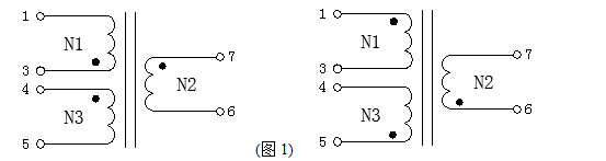
Follow In the normal manufacturing process of the transformer, there are two common situations that will lead to the same terminal error (or a certain winding phase is reversed): First, the PIN is connected in reverse. Take Figure 1 as an example. If other conditions remain unchanged, only the starting terminal of N1 and If the end ends are interchanged, the phases will be opposite, which is easy to understand; the second is to reversely insert the skeleton (which can also be understood as changing the winding direction, that is, interchange clockwise and counterclockwise), with horizontal EF25 (5+5PIN) Take the skeleton as an example. If PIN1-5 is wound with N1 (3-1) facing outward, and PIN6-10 is wound with N1 (3-1) facing outward, the phases will be exactly opposite. The above two points have been verified.
After understanding the above information, here are two examples to briefly illustrate the application of the above knowledge in design
Example 1. The customer information requirements are as follows: BOBBIN:EPC19 5+6PIN
N1 4-5:φ0.3*1P*72Ts
N2 1-2:φ0.3*1P*6Ts
N3 7-6:φ0. 3*1P*18Ts
N4 11-10:φ0.3*1P*4Ts
Conventional winding method:
PIN1-5 faces outward, starting end and the end end refer to the data requirements
The results of winding 4-5 are shown in Figure 3:
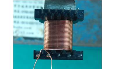
As can be seen from Figure 3, the start end and the end end intersect. Since the enameled wires at the start end and end end will be damaged during soldering, it is easy to cause If there is a short circuit, a Teflon sleeve will be added to enhance the insulation, thus increasing the production cost. The conditions for the other windings are the same.
Adjust the winding process:
PIN1-5 faces outward, and the start end and end end are interchanged
N1 5-4:φ0.3*1P* 72Ts
N2 2-1:φ0.3*1P*6Ts
N3 6-7:φ0.3*1P*18Ts
N4 10-11 :φ0.3*1P*4Ts
The result of winding 5-4 is shown in Figure 4:
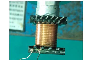
As can be seen from Figure 4, the starting end and the ending end do not intersect, and the conditions of the remaining windings are the same.
Summary: The end of the same name is a relative quantity. There are two ends of the same name of the winding instead of one. The end of the same name is related to the starting end, but it is not a corresponding relationship. Of course, there are other adjustment methods in Example 1. Here is No more details.
Example 2. The data requirements are as follows: SMD EE16 6+6
N1 6-4:φ0.3*1P*60Ts
N2 8-9: φ0.3*1P*8Ts
Conventional winding method:
PIN1-6 should face outward
N1 6-4:φ0.3*1P*60Ts
N2 8-9:φ0.3*1P*8Ts
The results are shown in Figure 5:
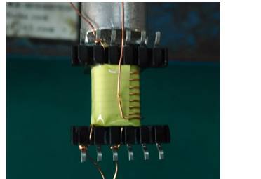
As can be seen from the picture above, when winding N2, the incoming and outgoing wires are close to the fixture end (Chuck), the lead hanging feet are not easy to operate, which consumes man-hours and increases the production cost.
Adjust the winding process:
When winding N1, PIN1-6 faces outward 6-4: 0.3*1P*60Ts
When winding N2, PIN7-12 facing outward 9-8: φ0.3*1P*8Ts
The result is shown in Figure 6:
As can be seen from the above figure, when winding N2, the lead hanging pin is easy to operate.
Summary: Changing the direction in which the skeleton is inserted into the fixture changes the phase of the winding. Interchanging the positions of the start end and the end end also changes the phase of the winding. Since "negative and negative make positive", there will be no Same name as terminal error.
The above-mentioned process changes also have limitations. In some cases, they cannot be changed easily. For example, 1. The number of winding turns is small or the span is large. Assuming that the number of winding turns is 1T, 1.1Ts and 0.9 will appear before and after adjustment. T, relatively speaking, the error will be very large; 2. It is recommended not to change the transformer that has been sent to safety regulations or has been mass-produced; 3. There are other unknown problems that may exist. Of course, generally changing the transformer winding process requires communication with the customer or sending samples for confirmation, so if conditions permit, you can try to change it!
Summary: 1. The transformer has two sets of terminals with the same name. Generally, customers will provide a group of terminals with the same name, which is not the starting terminal of the winding. 2. Changing the direction of the bobbin to insert the PIN or changing the position of the starting and ending ends of the winding can change the phase of the winding. If the phases of all windings are the same, the same ends will be the same. In the design process, the above relationships need to be flexibly used to design a more reasonable transformer!
