-
Mail us
contact@tiger-transformer.com -
Phone us
(+86)15655168738 -

Mail us
contact@tiger-transformer.comPhone us
(+86)15655168738
The flyback switching power supply is mostly used in the low and medium power range, such as 2w~100w.
Basic principle of flyback power supply
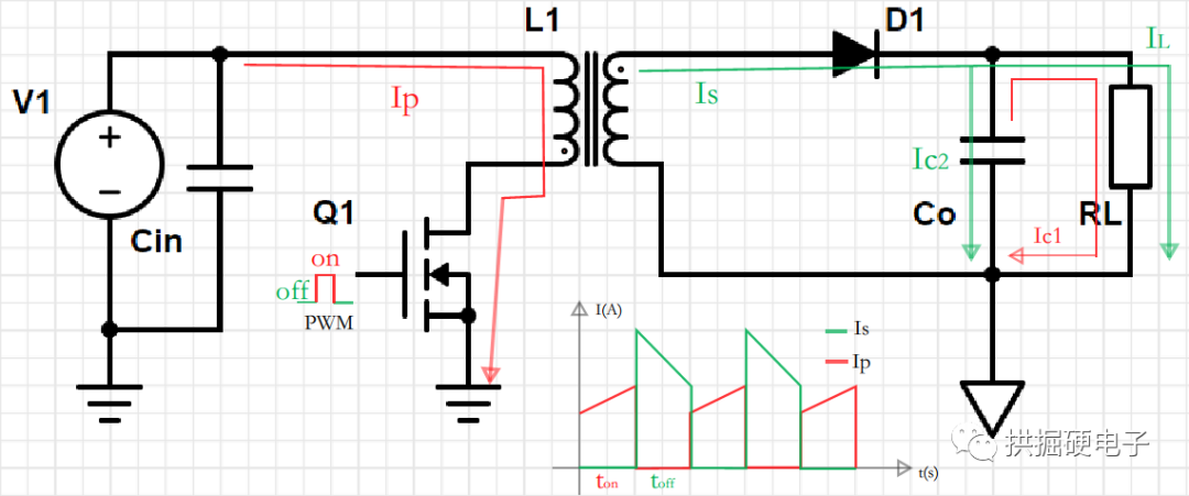
When the power supply is in a steady state, at the time ton, the MOS transistor Q1 is turned on, and the inductor current of the primary winding Lp increases linearly, see the flow of the inductor current Ip path. The capacitor Co supplies power to the load RL, see the path of the capacitor discharge current Ic1 in the figure below. Because the non-inverting terminals of the primary winding Lp and the side winding Lp of the transformer used in the flyback switching power supply are opposite. At time ton, the primary winding suppresses the increase of the current, the induced voltage of the primary winding is positive and negative, the induced voltage of the side winding Lp is negative and positive, and the diode D1 is in the cut-off state.
At the toff moment, the MOS is turned off, the energy stored in the primary winding is transmitted to the secondary winding, the primary winding maintains the original current direction, the induced voltage of the primary winding is negative and positive, and the induced voltage of the secondary winding Lp The top is positive and the bottom is negative, the diode D1 is in the conduction state, and the secondary winding supplies power to the capacitor Co and the load RL through the diode D1. See the flow path of the secondary winding current Is in the figure below.
CCM Vs. DCM
In a steady state, the flyback switching power supply has two operating modes: continuous mode Continuous Conduction Mode (CCM) and discontinuous mode Discontinuous Conduction Mode (DCM).
If within one switching cycle of the MOS tube, the current of the primary winding does not increase linearly from zero at the beginning of the next cycle, and the minimum current of the primary winding is not zero, we put the switching power supply This working mode is called continuous mode, or CCM.
If within a switching cycle of the MOS tube, TOFF is relatively long, so that the current in the primary winding is completely discharged, and the energy in the primary winding is completely transferred to the secondary. At the beginning of the next cycle, the MOS is turned on, the current of the primary winding increases linearly from zero, and the minimum current of the primary winding is zero. We call this working mode of the switching power supply a discontinuous mode, that is, DCM.
The following is a comparison of the current waveforms of continuous mode CCM and discontinuous mode DCM. Where Ip is the primary winding current and Is is the secondary winding current. It can be seen from the figure that the minimum current of CCM is not zero. The minimum current of DCM is zero, and there is a dead zone time tdead within the toff time, and both Ip and Is are zero.

For CCM flyback power supply, when the input voltage changes , possibly converting from CCM to DCM. It can be seen from the figure that the difference between CCM and DCM is reflected in the ratio of the current variation to the average current, and the inductance value of the primary winding of the transformer can be calculated uniformly through KRF.

Pin refers to the maximum input power, Lm refers to is the inductance value of the primary winding of the flyback power transformer, Vdc min refers to the minimum value of the DC input voltage, Dmax refers to the maximum duty cycle, fs refers to the switching frequency of the MOS tube, IEDC is the average current of the primary winding, Ids peak It is the peak current of the MOS tube and the peak current of the primary winding of the transformer.
The key waveforms of CCM and DCM, you can refer to the following figure:

CCM and DCM have their own advantages and disadvantages, and both work modes are commonly used in the flyback power supply. Now the advantages and disadvantages of the two are listed in the following table:
| Work Mode | CCM | DCM | Description |
|---|---|---|---|
| Efficiency | ☆ | DCM has no diode reverse recovery loss, has higher Coss×Uds² loss, and the overall DCM efficiency is better. | |
| Ripple | ☆ | The windings on both sides of the transformer of the DCM are fully charged and discharged , so the current ripple is larger. | |
| Output capacitor size | ☆ | DCM ripple current is larger, the output capacitor size is required bigger. | |
| Transformer size | ☆ | ①The inductance value of the transformer used by DCM is small and the size is smaller. ②CCM winding current has a large DC component, which can easily saturate the magnetic core, so it is necessary to increase the air gap in the magnetic circuit, thereby increasing the size of the transformer. | |
| Diode reverse recovery loss | ☆ | ①When DCM applies a reverse voltage to the output diode , the secondary winding current is zero, the diode is turned off with zero current, and no reverse recovery phenomenon occurs, so there is no diode reverse recovery loss. ②CCM applies a reverse voltage to the conducting output diode (the secondary winding current is not zero), and the diode recovers in reverse, with reverse recovery loss | |
| stability | |||
| td> | ☆ | ①The transfer function of DCM is a first-order system with fast transient response and easy stability. ②The transfer function of CCM has the right-half-plane zero point problem, and the feedback compensation is more complicated, which is not conducive to stability. When the duty cycle is ≥50%, slope compensation needs to be added. |
How to choose the working mode of the flyback power supply
Usually, the two working modes of CCM and DCM are in the same switching power supply It is possible to coexist in it, and it will switch as the input voltage and load change. When the input voltage is high and the load is light, the switching power supply works in DCM. When the input voltage is low and the load is heavy, the switching power supply works in CCM. According to the application conditions of the switching power supply, the transformer is preferably designed according to one of the working modes.

Under the same power conditions, if the space and cost The above requirements are relatively strict and DCM is recommended.
In the case of low output power (below 50w), the switching loss of the power supply is the main loss, and it is recommended to choose DCM.
When the output power is large (50w~100w), the on-state loss of the power supply is the main loss, and it is recommended to choose CCM.
