-
Mail us
contact@tiger-transformer.com -
Phone us
(+86)15655168738 -

Mail us
contact@tiger-transformer.comPhone us
(+86)15655168738
The difference between the continuous mode CCM and the discontinuous mode DCM of the flyback switching power supply is mainly reflected in the transformer design. This article expands to explain which technical parameters of the flyback power supply will be affected by DCM.
If you want to set the flyback switching power supply in discontinuous mode DCM due to the limitation of space size and material cost, you need to set the duty cycle of the MOS tube to be less than 50%, and usually set the maximum duty cycle to 45% , to reduce the inductance value of the transformer, thereby reducing the size of the transformer.
Primary Winding Inductance
In In discontinuous mode DCM, the formula for calculating the inductance value of the primary winding of the flyback power transformer is as follows:

The above figure contains four formulas, where Pin refers to the maximum input power, Po refers to the maximum output power, Po=Pin×power conversion efficiency, the conversion efficiency can be 0.8, you can see The essence of the first three formulas is the same, and they are all derived from the inductance energy storage P=0.5×Lp×Ip² at the time when the MOS tube is turned on, and the volt-second product Uin×ton=L×Ip, D=ton/T, but The formulas are written differently. The fourth formula is derived based on the inductive energy storage P=0.5×Lp×Ip² at the time when the MOS transistor is turned on, and the basic definition of power (power is the energy per unit time).
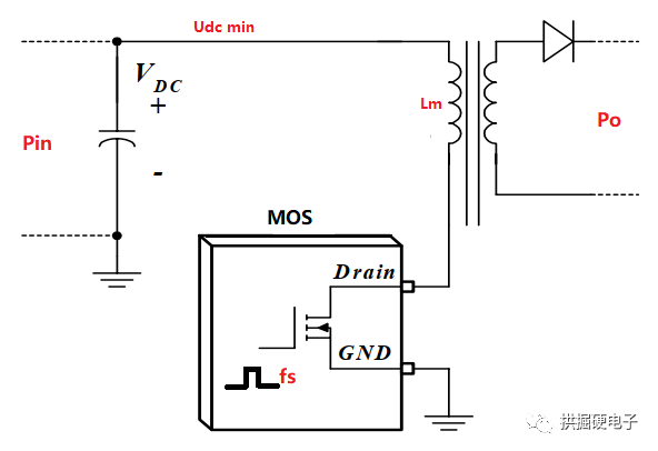
Supplementary explanation of the formula, Lm refers to the inductance value of the primary winding of the flyback power transformer, Vdc min refers to the minimum value of the DC input voltage, Dmax refers to the maximum duty cycle, fs refers to the The switching frequency of the MOS tube. Through the above formula, the inductance value of the primary winding of the transformer can be calculated.
When the inductance value of the primary winding of the transformer is determined, the peak current of the primary winding can be calculated.
Primary winding peak current
Set Ipk to be the peak current of the primary winding, let Iav be the average current of the primary winding, then when the power supply is set to DCM, Iav=0.5×Ipk× Dmax=Pin/Udc min.

Secondary winding peak current and current RMS
Let Irms be the effective value of the primary winding current, let Ispk be the peak current of the secondary winding current, let Isrms be the effective value of the secondary winding current, then when the power supply is set to DCM, Ispk=Ipk×turns ratio , Irms=Ipk×√(Dmax/3), Isrms=Ispk×√((1-Dmax)/3).

Feedback loop
Set reverse The excitation source is a discontinuous mode DCM, which will affect the design of the above parameters. In addition, the feedback compensation loop of DCM is relatively simpler than that of CCM. The following figure is a typical application circuit to realize the stability of the flyback switching power supply system, in which the resistor R3 and capacitor C1 are the frequency compensation network, and the recommended value range of R3 is 1k20k, the recommended value range of C is 100nF470nF.

